Update (26/3/02) Electricity outlet definition:
Old estimates regarding the number of electricity out lets and locations
have been updated and submitted to ST/EL after detailed discussion in the
ID-SR1 meetings.
The following document has been submitted to ST/EL for planning: it
will be used to check feasibility and costs. docpdf
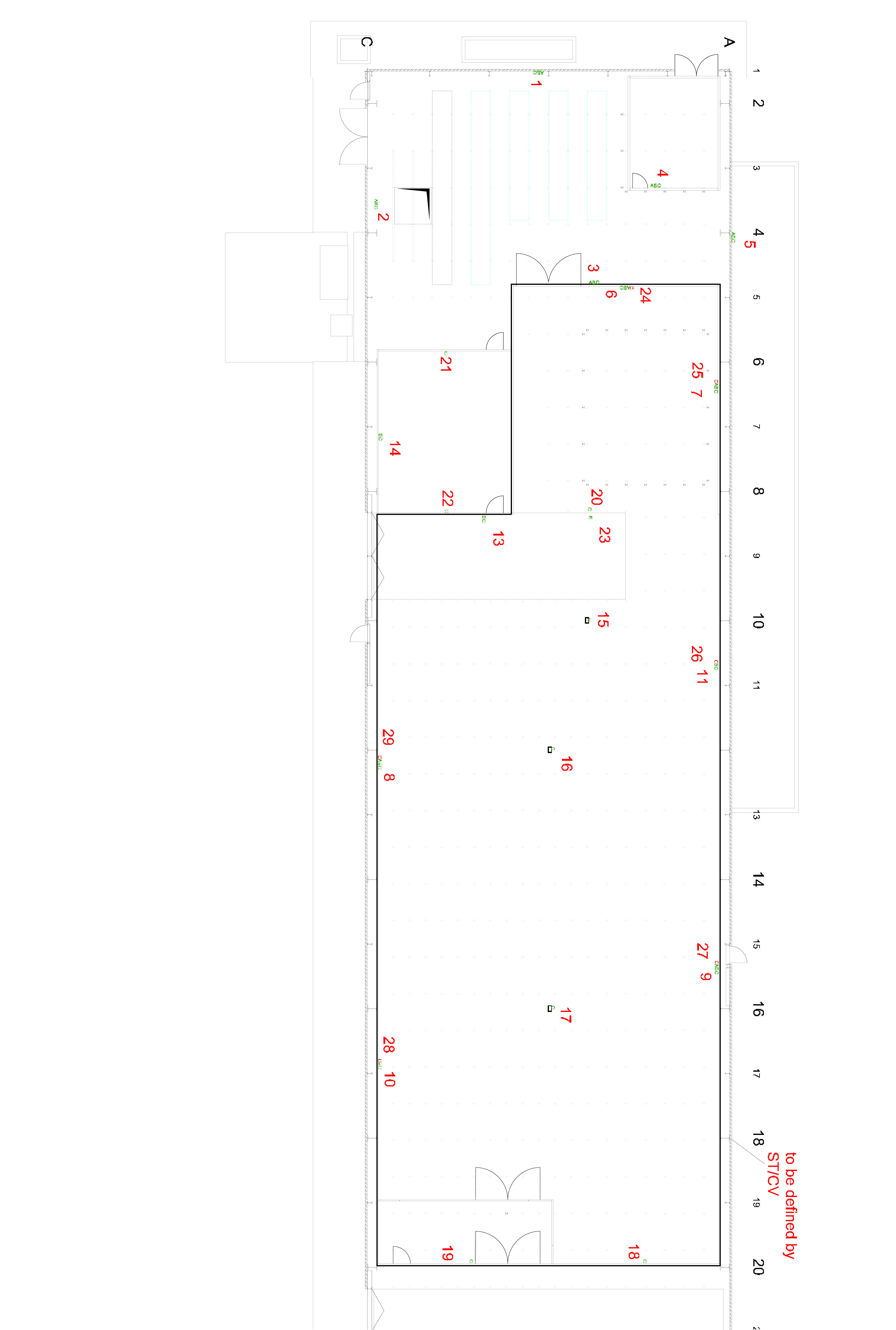
The document forsees the following (Click on picture to get eps file):
| Outlet_number | Outlet_types | Comment |
| 1 | 1x380/16&2x220/16&4x220/10 | |
| 2 | 1x380/16&2x220/16&4x220/10 | |
| 3 | 1x380/16&2x220/16&4x220/10 | |
| 4 | 1x380/16&2x220/16&4x220/10 | |
| 5 | 1x380/16&2x220/16&4x220/10 | |
| 6 | 1x380/16&2x220/16&4x220/10 | |
| 7 | 1x380/16&2x220/16&4x220/10 | |
| 8 | 1x380/16&2x220/16&4x220/10 | |
| 9 | 1x380/16&2x220/16&4x220/10 | |
| 10 | 2x220/16&4x220/10 | |
| 11 | 2x220/16&4x220/10 | |
| 13 | 2x220/16&4x220/10 | |
| 14 | 2x220/16&4x220/10 | |
| 15 | 4x220/10 | |
| 16 | 4x220/10 | |
| 17 | 4x220/10 | |
| 18 | 4x220/10 | |
| 19 | 4x220/10 | |
| 20 | 4x220/10 | |
| 21 | 4x220/10 | |
| 22 | 4x220/10 | |
| 23 | 2x220/16 | |
| 24 | 4x220/10 | OnUPS |
| 25 | 4x220/10 | OnUPS |
| 26 | 4x220/10 | OnUPS |
| 27 | 4x220/10 | OnUPS |
| 28 | 4x220/10 | OnUPS |
| 29 | 4x220/10 | OnUPS |
| Note 12 does not exist anymore |
Drawings from 26/03/02 as dwf and dwg files (view with AutoDesk WHIP!). Note: this is not an official drawing, just our "working drawing" for our planning. ST keeps the only official drawings for SR1
Drawings from 06/03/02 as dwf
and
dwg
files (view with AutoDesk
WHIP!). Note: distribution of electrical connections was discussed
and has changed since then (to be updated)
(click on images to enlarge)
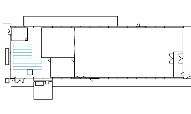
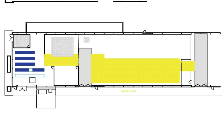
The drawing used for the following locations is here.
(Acad DWG file)
The assembly area and test area will be (as required by the 1AHU-ventilations
system) one room. Separation between the two will be done by a fence &
gate.
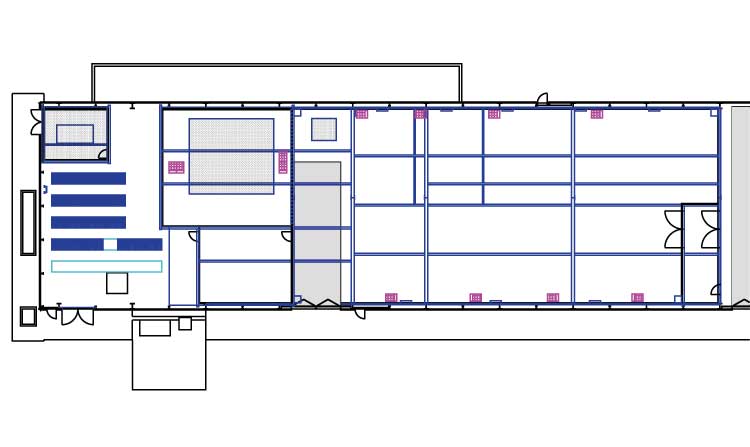
Based on the estimates of numbers
of racks for SCT,TRT,PIX , the racks are distributed with emphasis
on minimal cable length. Priority is given in order of: low/high voltage
supply - DAQ - UPS+DCS.
The rack arrangements still needs to be verified by DAQ,DCA,PS experts.
Pixel will not test in TA but only in AA.
(Note coloured lines from racks to TA are arbitrary)
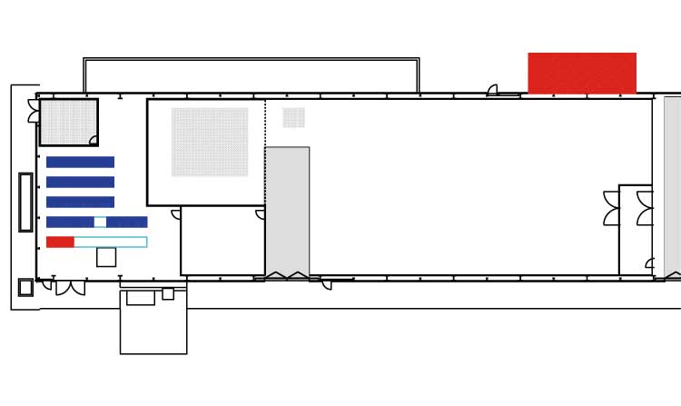
Rack Positions as PDF
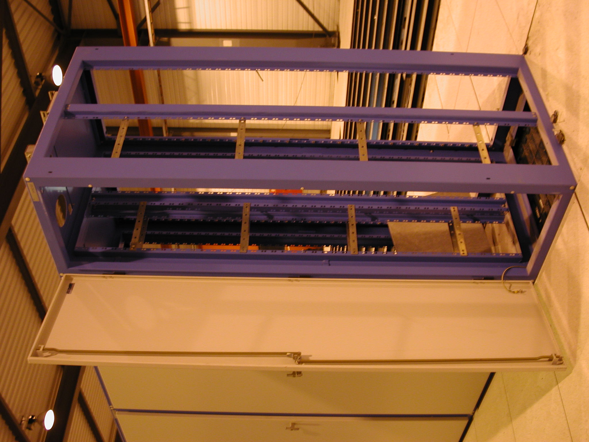
The proposal is to use existing racks
to
allow services to pass from under the false floor to the assembly area.
The racks have a floor area of 60x90cm.
In the TA: 4 racks are placed on existing floor rails. We plan to access the two racks closer to the rack room directly through the wall to minimize services length. The other two racks in the TA are likely to be served through the floor.
In the AA: 8 racks are placed along the wall. Note that the exisiting
panels along the wall are partically covered by the wall itself. The rack
may either be rotated by 90 degrees ( as shown in the drawing) or be partically
enbedded in the wall like the diffusers). The first option results in a
modification of the rails underneath the rack.
To be discussed in more details.
The drawn racks are to mark approximately their position.
NOTE: Diffuser locations are APPROXIMATE and taken from older drawings. Their positions have to be updated for the new ventilation system and the rack location be adjusted accordingly.
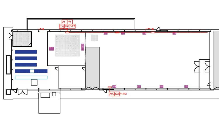
Assume that He and Nitrogen are feed from batteries outside of the
building on the concret slap along both long sides of the building.
To bring in the gas: run main supply pipe (1 CO2, 1He, 1N2, 1 spare)
outside of building.
Drill 2 holes (30cm diameter, center of hole 1.5m above false floor)
on rear building wall and 1 hole in front side og building. Eack hole has
>=4 pipes cemented in (diameter to be defined)
For the gas distribution two panels (size of 60x40x30 = length,height,depth) are assumed in the AA for PIX and SCT along one wall and two panels for TRT along the other wall. The TA has one panel of 100x40x30cm.
Based on previous discussion: add reinforced panels at 2000kg/m2 max load in TA and AA.
Each panel is assumed to be 60x90cm to match the existing rails (0.54m2).
The total area is approximately 300m2
Note: reinforcement platform to CMM slab has been added
the 1-AHU system is located at the rear wall on the outside .